ROVER COMMUNICATIONS // MECHANICAL DESIGN

ANTENNA ROTATOR

A geared rotation mechanism for a tripod-mounted antenna.

PROGRAM SNAPSHOT

ROLE

Mechanical design and fabrication

BUILD

Printed parts, reused hardware, machined plate

STATUS

Prototype motion demonstrated

ROVER COMMUNICATIONS // MECHANICAL DESIGN

ANTENNA ROTATOR

A geared rotation mechanism for a tripod-mounted antenna.

As the rover moves sideways across a mission area, it can leave the directional antenna's coverage. The antenna needs to turn to follow that change in direction. I designed and fabricated the mechanism that lets it rotate on a tall tripod.

MISSION

Allow the tripod-mounted antenna to change direction as the rover moves across the mission area.

ROLE

I designed and fabricated the complete mechanism and briefly tested its motion with temporary electronics. My work focused on the mechanics; I did not develop the control software.

SYSTEM

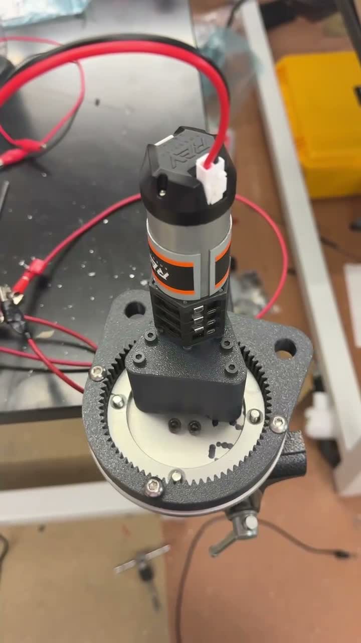
A small gear driven through a planetary gearbox engages a large ring gear. Printed parts and a machined plate mount the mechanism around the tripod assembly.

CONSTRAINTS

Keep costs down by using components already available to the team, and work out how to support the antenna while allowing it to rotate.

ANTENNA ROTATOR

The assembled drive during a brief motion test.

TOOLS USED

CAD3D printingMachiningGear drive

VALIDATION / TESTING

Brief powered motion check with temporary electronics.

Video records the gear mechanism moving and the mounted antenna rotating.

Top-down view of the gear mechanism in motion.

SYSTEM

A Gear Drive Built Around Available Hardware

I used a small gear driven through a planetary gearbox to engage the large ring gear. Reusing components we already had helped keep the build inexpensive. Most of the custom geometry was 3D printed.

The main mechanical problem was how to mount and support the antenna while giving it a way to turn. The top-down clip shows the drive and rotating structure during a powered check.
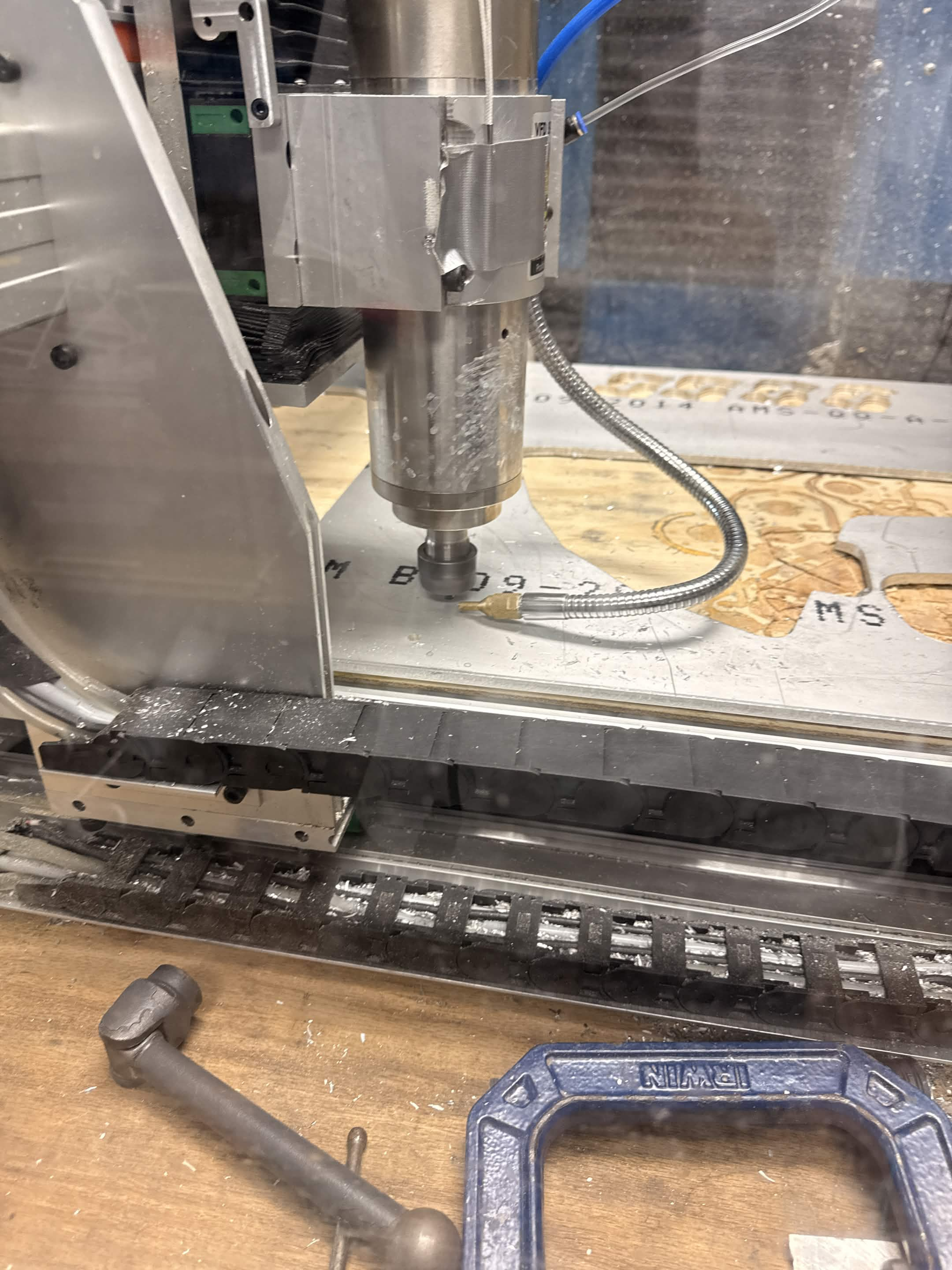
The mounting plate during machining.
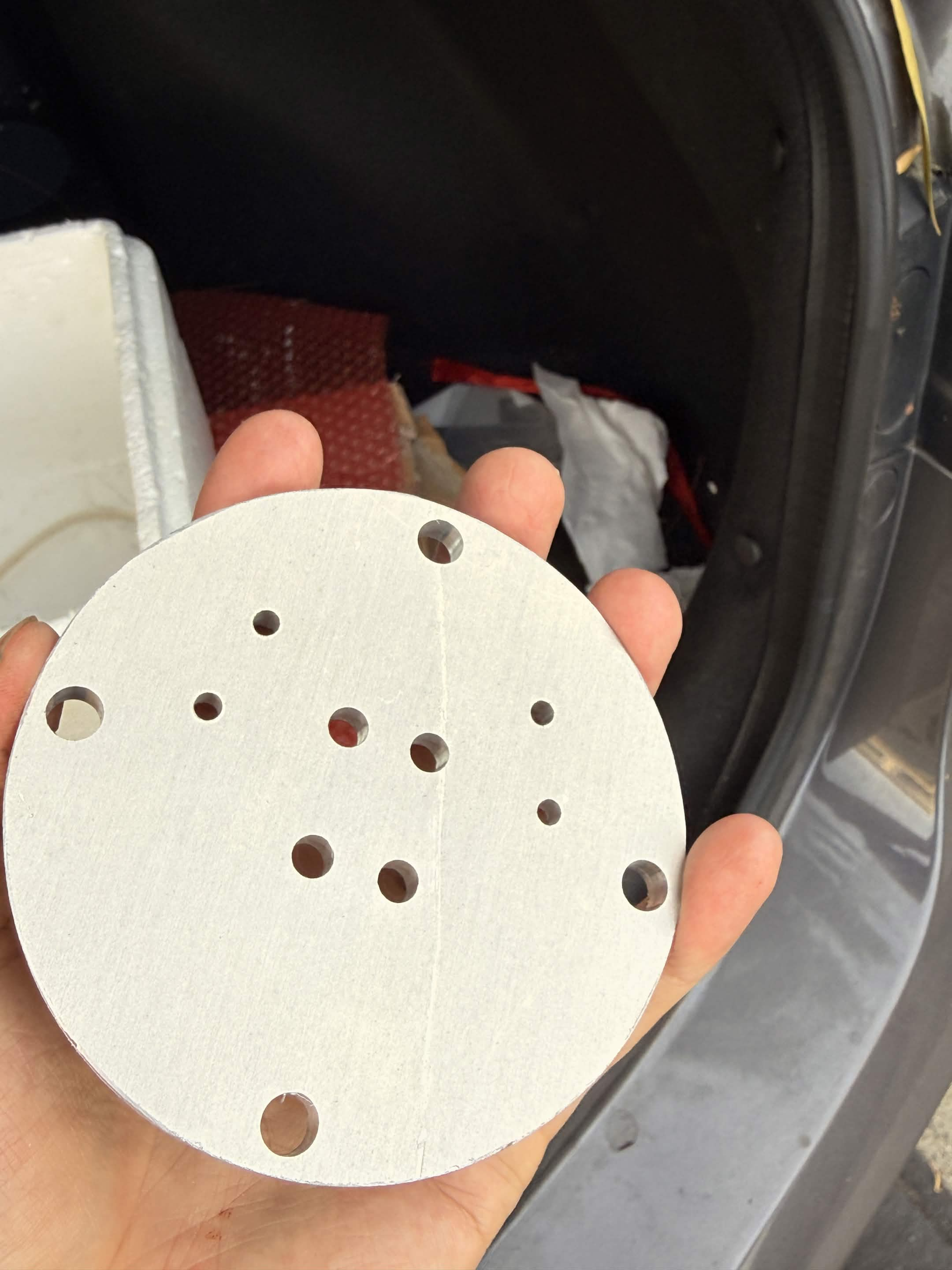
Holding the finished mounting plate.

The mounting plate during machining and after fabrication.

FABRICATION

Machined Mounting Plate

I designed and fabricated the rotator using mostly 3D printed parts and off-the-shelf components we already had. This mounting plate was the one part I machined for the assembly.

Powered rotation of the mounted antenna assembly indoors.

ASSEMBLY

The Antenna in Motion

With the antenna mounted, I briefly ran the mechanism using temporary electronics. This clip shows the assembly turning on the tripod. The goal was modest changes in pointing direction as the rover moved across the mission area.

A Simpler Bearing Arrangement Next Time

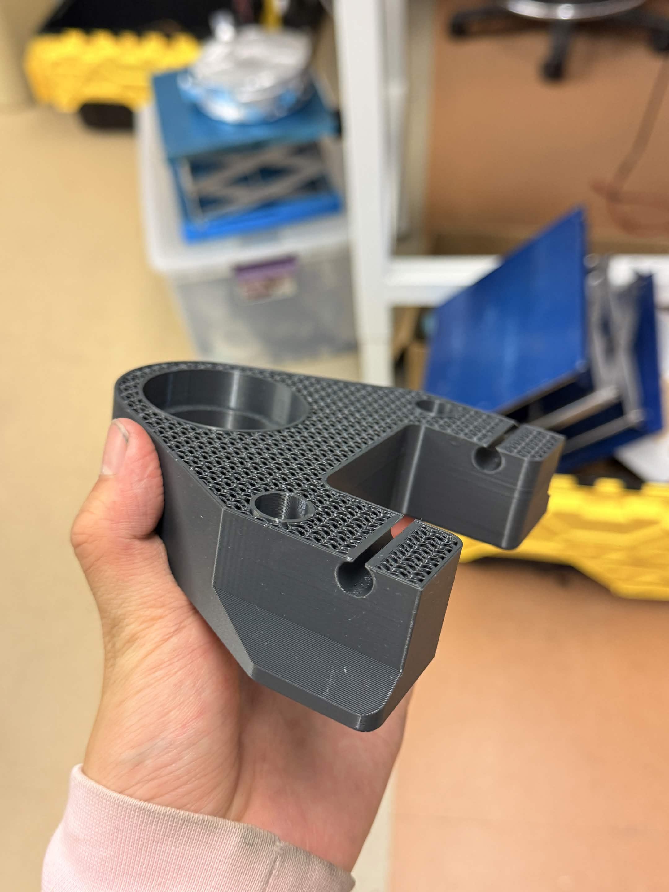
A failed print with the internal infill and walls exposed.

DESIGN REFLECTION

A Simpler Bearing Arrangement Next Time

I used thrust bearings, needle bearings, and a large turntable bearing in the assembly. Looking back, I think I overcomplicated the support arrangement for the motion this antenna needed. A simpler bearing arrangement is the first thing I would revisit.

This failed print exposes the infill and internal walls of one of the printed parts.