DECISION 01
KEPT THE PROVEN CHASSIS AND SPENT TIME WHERE IT MATTERED
Constraint
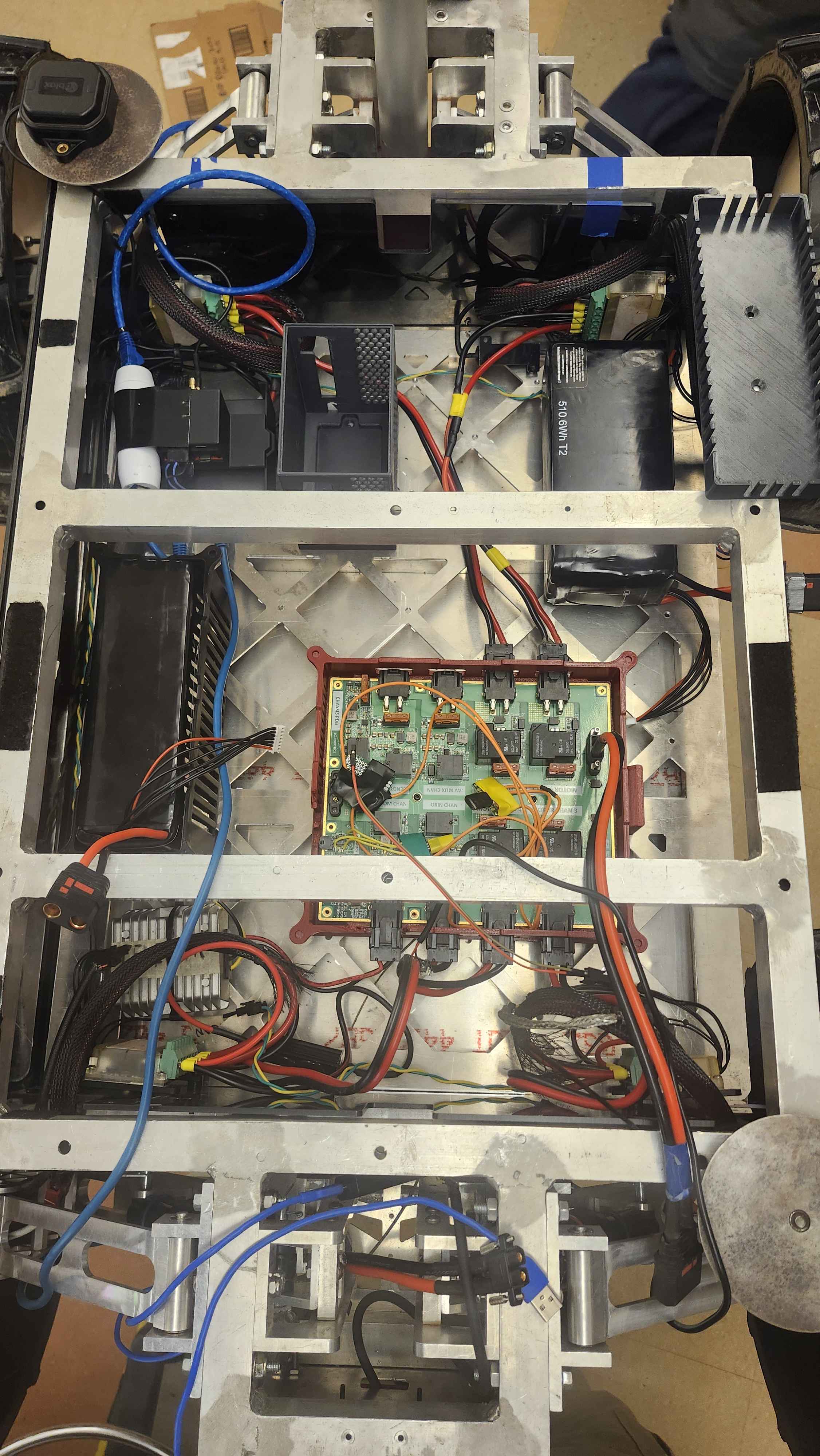
The welded aluminum chassis already worked. The real issues were wheel performance, manipulator mass, electronics access, payload packaging, and how quickly the rover could be serviced during testing.
Decision
Kept and rebuilt the chassis instead of replacing it, then focused redesign time on the weak points that were actually limiting field performance.
Impact
That kept the season grounded and freed time for the changes that improved the rover most.