2026 ROVER MANIPULATOR // ARM REDESIGN

2026 ROVER MANIPULATOR ARM

A task-focused 4-DOF + linear-axis arm designed to replace a heavier 6-DOF system while still meeting competition manipulation requirements.

PROGRAM SNAPSHOT

ARCHITECTURE

4 rotational DOF + lateral linear axis

REACH

About 32 in from the shoulder pivot, with the pivot roughly 10-12 in off the ground

LOAD TARGET

5 kg peak load with 1.25 safety factor

2026 ROVER MANIPULATOR // ARM REDESIGN

2026 ROVER MANIPULATOR ARM

A task-focused 4-DOF + linear-axis arm designed to replace a heavier 6-DOF system while still meeting competition manipulation requirements.

The 2026 rover manipulator replaces our heavier 2025 6-DOF competition arm. The older system had more theoretical freedom, but it weighed about 17 kg, used larger and more complex drivetrains, and went beyond what the University Rover Challenge tasks realistically required. The new design uses four rotational degrees of freedom mounted on a lateral linear axis, trading some universality for a lighter, cleaner, task-matched architecture that came in around 11 kg.

The arm reaches roughly 32 inches from the shoulder pivot, with that pivot roughly 10-12 inches off the ground. The joints are shoulder pitch, elbow pitch, wrist pitch, and wrist roll. The rail shifts the arm's working plane left and right, giving the rover lateral reach without adding another shoulder yaw joint. That layout is not more capable in every way. It is a more intentional competition manipulator designed around panel interaction, object pickup and delivery, and the real task set the rover actually sees at URC.

ARCHITECTURE

4 rotational DOF mounted on a lateral linear rail axis.

REACH ENVELOPE

Roughly 32 in max reach from a shoulder pivot about 10-12 in off the ground.

LOAD TARGET

Designed around a 5 kg peak competition load, with typical task objects closer to 0-3 kg.

DESIGN TRADEOFF

Less universal than the old 6-DOF arm, but lighter, simpler, and better matched to the rover's actual tasks.

ARCHITECTURE

Subsystem Breakdown

Major mechanism highlights are given more weight, while supporting sections stay quieter and easier to scan.

TOOLS USED

SolidWorksFusion 360 CAMFEACNC aluminum plateBall screwLinear railsTiming beltsCOTS punched tubing3D printed CF gearsMechanical packaging

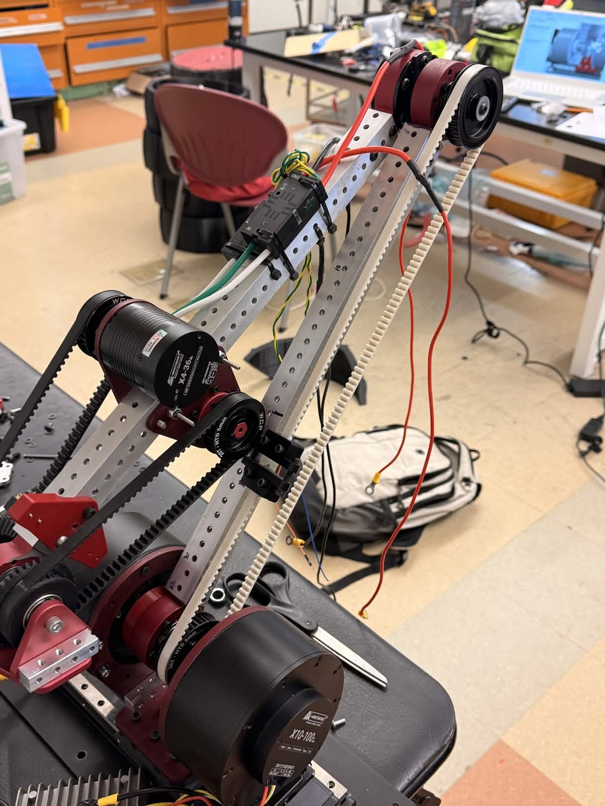
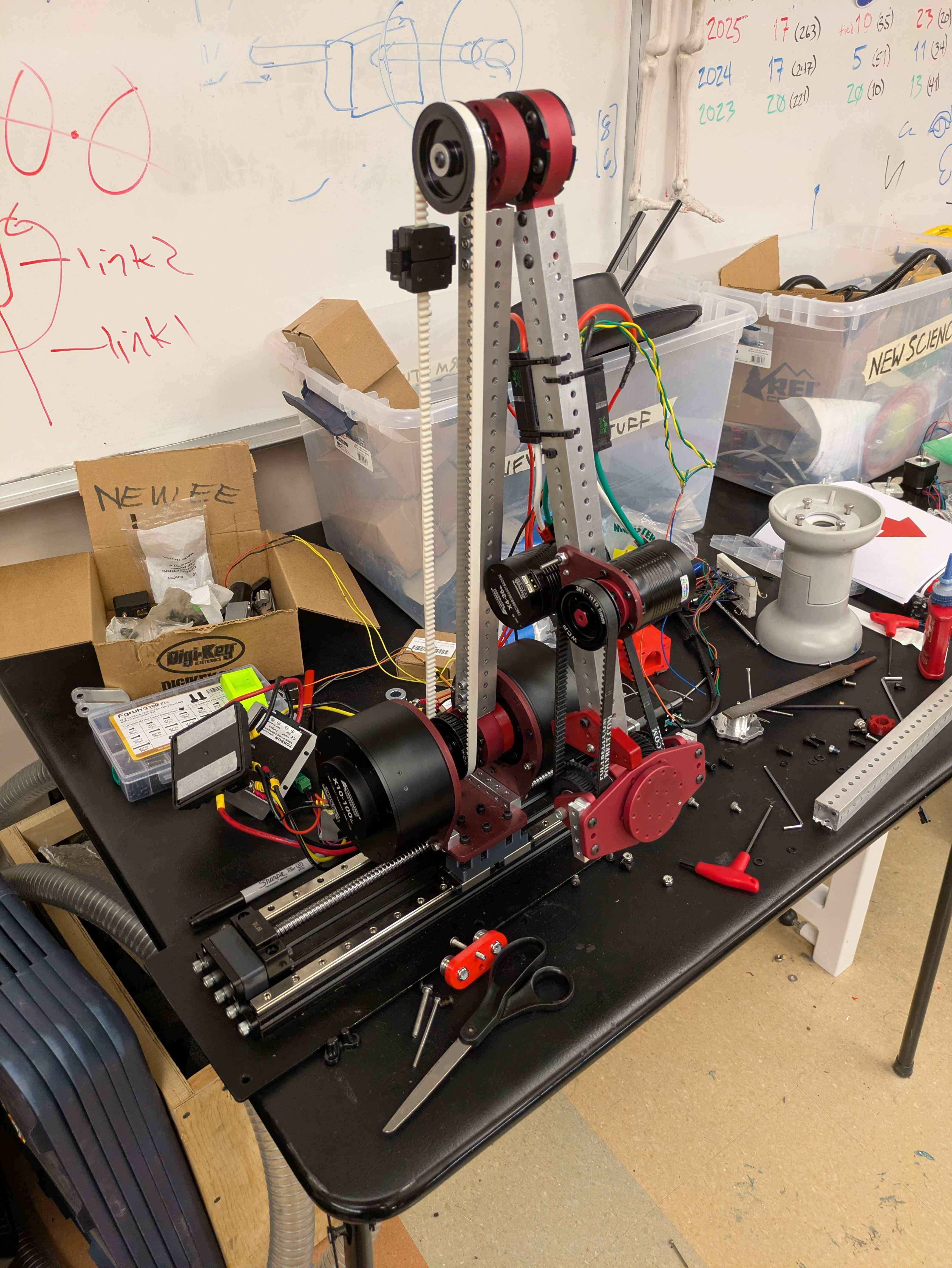
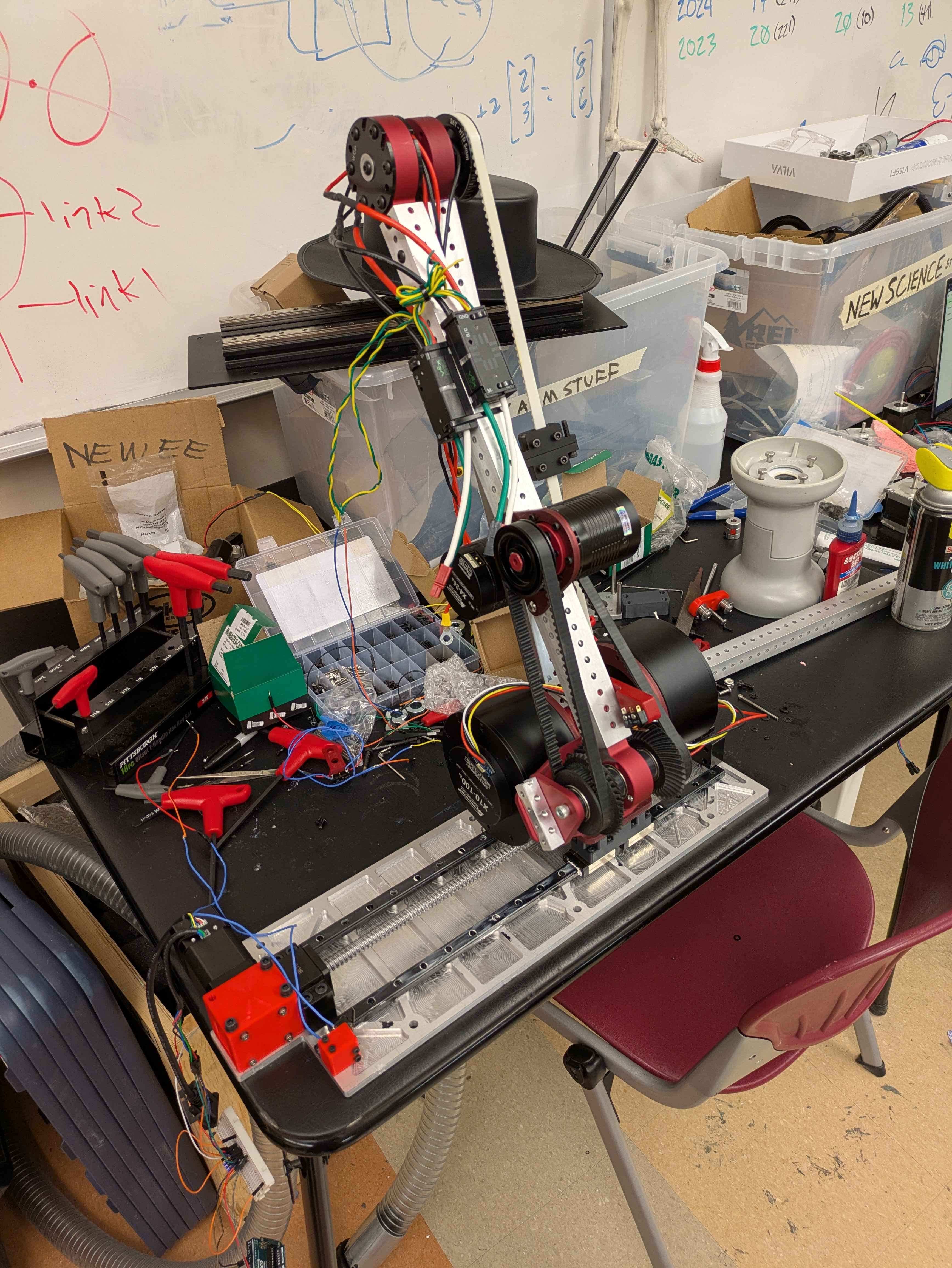
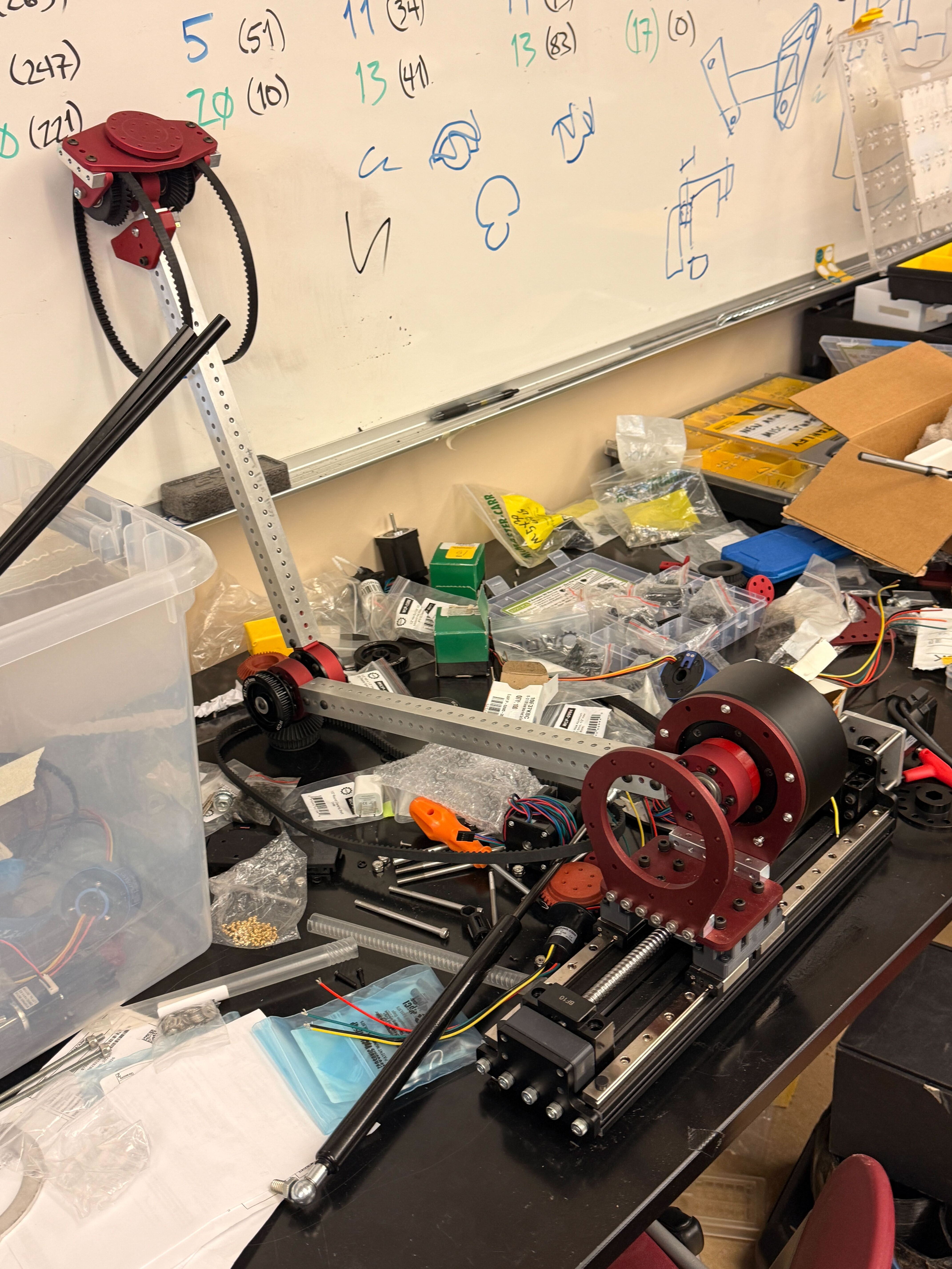
Earlier arm direction before the redesign, representing the heavier and more universal approach we moved away from.

DESIGN PROBLEM

Replacing an Overbuilt 6-DOF Arm

Previous direction | heavier drive stack | longer reach

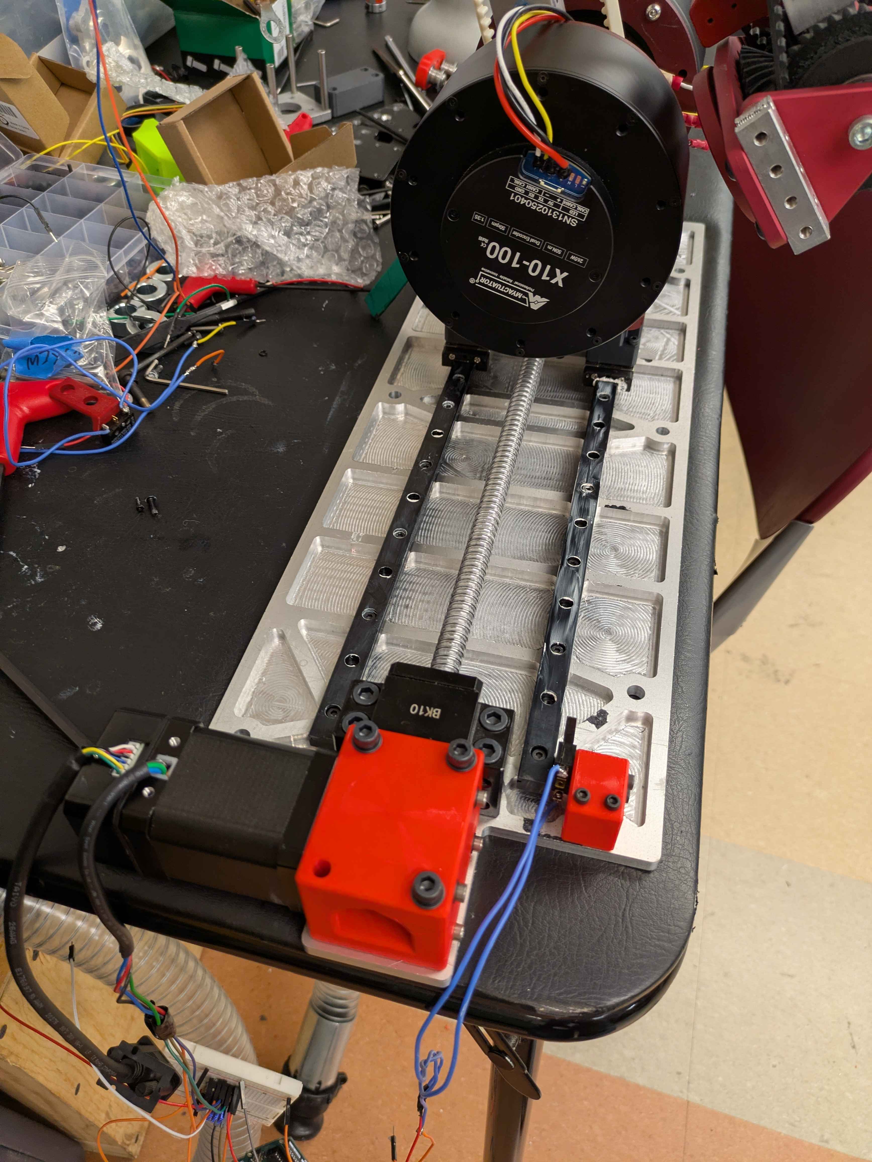
The 2025 competition arm had more theoretical freedom, but it came with a heavy drive stack, longer reach, and more complexity than the task set realistically demanded. It weighed about 17 kg and used large COTS harmonic drives along with custom cycloidal gearboxes.

For 2026, the goal was not to build the most universal arm possible. The goal was to build a manipulator that could satisfy the University Rover Challenge requirements while giving the rover more weight margin, cleaner integration, and a newer system to present at competition.

CAD view of the new manipulator layout, showing the 4 rotational joints plus the lateral linear axis.

ARCHITECTURE

4-DOF Arm on a Linear Axis

4 rotational DOF | lateral rail | task-focused workspace

The arm primarily works in a vertical plane: reaching forward, upward, and downward. Its four rotational degrees of freedom are shoulder pitch, elbow pitch, wrist pitch, and wrist roll. The linear rail shifts that working plane left and right, giving the rover lateral reach without adding another shoulder yaw joint. If more lateral alignment is needed, the rover can also turn its chassis.

This architecture reduces the need for extra joints while still covering the useful task space. It is well matched to URC-style panel interaction tasks involving switches, keyboards, levers, knobs, and similar one-handed astronaut-style interfaces, along with object pickup and delivery. It also allowed the arm to be shorter, lighter, and easier to package.

Belted Layout Around Smaller Actuators

Built arm segment showing the smaller tube structure, belted joint layout, actuator packaging direction, and the turnbuckled tensioned open belt on the new arm.

ACTUATION AND STRUCTURE

Belted Layout Around Smaller Actuators

Smaller actuators | reduced reach | belts move mass inward

The new arm uses enclosed COTS MyActuator BLDC modules with integrated gearing and encoder feedback, in two actuator sizes selected for different joints. They are cleaner to package than the older motor plus harmonic and cycloidal drive stack, but they are also weaker. The rest of the arm was designed around that constraint.

Reach was reduced from roughly 48 inches to roughly 32 inches, the structure moved to smaller COTS punched tubing, and belt transmissions were used to place motor mass closer to the base where possible. Instead of solving the problem with larger actuators, the design reduces the loads the actuators have to carry.

Built Once, Slimmed Down, Rebuilt before
Built Once, Slimmed Down, Rebuilt after

Before-and-after comparison of the linear-base revision, from the extrusion-supported prototype to the pocketed 1/4 inch plate.

LINEAR BASE ITERATION

Built Once, Slimmed Down, Rebuilt

Prototype base | pocketed 1/4 in plate | ~1 kg saved

The first linear-base revision used a 1/8 inch plate with aluminum extrusion added for stiffness. It worked, and we manufactured it, but the built assembly was bulkier and more complicated than it needed to be. After review, we revised the structure into a single highly pocketed 1/4 inch aluminum plate.

The revised plate provides stiffness directly, removes the extra extrusion and bracket structure, and saves roughly 1 kg. The pockets do not cut fully through; a thin lower skin remains mostly for dust protection. The stepper was also rotated 90 degrees so it no longer protrudes from the side of the assembly.

Built Baseplates before
Built Baseplates after

Built baseplate comparison between the first version and the revised hardware, showing the flatter revised build and the removal of extra structure around the linear axis.

Bench test of the compact differential wrist and printed gear geometry.

WRIST AND END EFFECTOR

Compact Differential Wrist

Differential wrist | printed CF gears | compact package

The wrist uses a compact differential layout to combine wrist motion into a small package. Standard pulleys are embedded into custom curved bevel gears, allowing roll and pitch behavior without a much larger stacked mechanism. The differential also lets the wrist combine the output of two smaller motors, so the system still meets a minimum wrist safety factor of about 1.5 while using smaller actuators than a more conventional layout would need. The gears were generated in CAD and 3D printed in carbon-fiber-reinforced material because the geometry was unusual and the loads were moderate compared to the shoulder and elbow.

Prototype straight bevel gears in ASA CF.
Prototype straight bevel gears in PETG CF.
Current curved bevel gears in nylon CF.

Printed wrist gear iterations from early straight bevel experiments to the current curved bevel gear.

System Architecture and Mechanical Lead

In-progress hardware build showing the manipulator as an assembly problem as well as a CAD problem.

MY ROLE

System Architecture and Mechanical Lead

Mechanical lead | CAD ownership | build and integration

I led the overall design direction for the 2026 manipulator, including the system architecture, major tradeoff decisions, and packaging strategy. I owned the CAD for the shoulder-through-wrist assemblies and directed the baseplate and linear-axis revision. I also built and integrated the hardware, so my work covered both system-level design and practical assembly.

A Lighter Arm Built Around the Actual Task before
A Lighter Arm Built Around the Actual Task after

Built manipulator after the redesign, showing the final lighter layout that replaced the heavier 6-DOF direction.

RESULT

A Lighter Arm Built Around the Actual Task

Lighter arm | less reach by design | better task match

The final design is not a universal upgrade over the old 6-DOF arm. It has less reach and fewer degrees of freedom by design, and it sometimes relies on rover positioning for approach angle instead of solving every problem with extra joints. But that trade was intentional. The arm dropped from about 17 kg to about 11 kg, covers the actual competition tasks, and gives the rover more weight margin for the rest of the system.

GALLERY / APPENDIX

Supporting Media And Section Index

A compact appendix for scanning media, captions, and subsystem callouts without re-reading the full page.

Machined Baseplate Revision

BUILD PHOTO

Machined Baseplate Revision

Pocketed 1/4 in aluminum baseplate after removing the earlier extrusion structure.

Joint Detail

DETAIL

Joint Detail

Bolted joint plate and hub interface for one of the arm pivots.

Arm Segment

ASSEMBLY

Arm Segment

Partially built arm section showing tubing, belts, and motor placement.

Revised Baseplate Close-Up

BASEPLATE

Revised Baseplate Close-Up

Linear rails and ball screw mounted on the revised pocketed baseplate.

TEST

Linear Rail Test

Bench test of the linear base with the arm installed.